Projects
Climbing Handholds for Visually Impaired Climbers
Project completed in GEEN 2400 Project for the Community class fall 2022. Prompted to find clients within our community and create a solution to a daily problem they face. Through iteration and client feedback we were able to create a set of climbing holds that is controlled by an app to change color and brightness.
_edited.jpg)
Small Scaled Truss
Project completed in GEEN 2851 Statics class fall 2021. Was challenged to build a truss that could withstand 1200 lbs. of force. We captured the detailed process of constructing a truss by measuring bending and tension in each beam. We used these measurements to calculate a predicted value of how much force we thought it could hold.


Truss Project

Truss Drawings in CAD

Truss Calculations in MATLAB


Bending and Shear Testing Wood Specimen
The purpose of this group project was to demonstrate knowledge gained throughout the course of the semester by applying it in the real world. To do this we designed and built a truss with the goal of withstanding 1200 lbs. of force. We worked towards this goal by testing and calculating stresses and shear forces in different truss designs. During the design phase we decided that a simple truss would leave less room for error during the manufacturing process. We used programs like CAD and MATLAB to try out different truss designs. The warren truss is what we went with consisting of five triangles where the point load would act in the middle. When building our truss, we had to follow some assumptions in order to meet the requirements of a truss. None of the members could touch and all members had to be cut at a 90° angle. Some other requirements consisted of a size constraint of 22 - 23” in length, and a max height of 7”. Each member specifically had to be greater than 3” and the truss had to consist of more than 6 members.
The first thing we tested was the shear strength of the glue and the bending strength in the wood. We used the machines in the ITLL to test the failure load of our components. In both the shear test and bending test, our materials broke right down the middle of the member. The stress in our wood was about 1.5 ksi and the shear stress was about 1.3 ksi. We predicted the shear stress to be 1252.64 psi and the maximum beam stress to be 14.29 ksi. This data allowed us to analyze the numbers and calculate our max load and strength to weight ratio. Our predicted maximum load was 2658 lbs. and our predicted strength to weight ratio was 4437. Obviously there will be some error within the manufacturing process so we did not expect to hit out maximum load prediction. On test day our truss withstood 1084 lbs of force and its strength to weight ratio was 1391 lb/lb. This project was a great test of not only calculation skills but also our ability to bring the calculated values to life and were actually able to test and determine if our testing and manufacturing was successful.

Fabrication Process

Point Where Truss Broke After Force Test

Final Testing Values
Tea Light Candle Thermo System

Extended Syringe and Plunger

The objective for this project was to create a system that can lift two quarters by using the different components of thermodynamics that we learned in class. Some design constraints of the project were $30 budget, no embedded energy sources and no safety hazards. Our project began with initial ideas and testing to verify if our ideas would be reliable. After some trial and error my group decided to design a piston cylinder device. The materials needed were:
Our plan was to use the heat of a tea light candle to heat water in a flask, which then would increase the pressure in the flask and eventually push the piston up to raise the quarters that were taped on top. Some challenges we faced with this design was the construction of the plastic syringe. The syringes we bought at the store were only 8 cm tall, so it was not going to satisfy the 10 cm requirement. We decided we would try and attach two together. As seen in the video we marked with yellow tape where the 10 cm line was. The challenge we faced was in maintaining an airtight seal between the two syringes in order for the pressure to build up enough. After trying many different sealing methods, we found that moldable rubber was the best option. We also tested different bases that would inhibit the water to heat up faster but stuck with our original idea of the soda can base. This testing was very time consuming due to the time it would take to heat up the water. I am sure we could've created a better insulated system to speed up this process. The final video was time lapsed over the course of forty minutes, but we were able to complete the objective and raise the quarters. We even built up enough pressure to explode the plunger off the top.

REVIT Home Design
This project taught me what the design process looks like. Lots of editing and reiterations helped produce the final product I wanted. The concept for my home was to create a place to go when in need of quality time with friends and family. There are many great spaces within the home to host guests and the large windows allow as much sun as possible into the home. The site in in Holland, MI a town close to home for me. It is the perfect get away in the summer and a place people could use to escape the long winter months. To create the drawings seen below we used Revit for the floor plans and construction documents. I also had to learn how to use the rendering features in Enscape. These are very valuable tools because it allows the project to be brought to life. This project was a great experience because I had to use my creativity and skills together to create a final product.

Main Floor Plan

Upper Floor Plan

Front of House Rendering

Back of House Rendering

View from Lake Rendering
Climbing Handholds for Visually Impaired Climbers
Project Overview
Mission:
To improve the quality of climbing for visually impaired climbers
Target Audience:
Visually Impaired Climbers
Solution to Problem:
To create light up, hand holds with adjustable brightness and color so climbers can identify routes clearly in a variety of environments.
Client:
Local Boulder climber that has trouble differentiating between red, orange and pink routes. Also has a difficult time seeing route colors in dimly lit areas such as caves/overhangs.
Final Design
Our final design consisted of handmade holds made out of epoxy resin. The LEDs are controlled by an app interface called Blynk which communicates via Wi-Fi to a microcontroller (ESP32). There is daisy chain wiring that runs up the back of the wall/board that gives power to all of the Neo Pixel Rings that are placed inside the handhold. This set up is powered by a cord that is then plugged into a normal outlet and a power distribution box is used in order to get the correct number of amps to light up the holds.
.jpg)
Design Requirements
- User controllability
- Proper material for grip
- Cheaper price than alternatives
- Electronics that fit in hold
- Effective power source
- Strength of hold
Design Process
The first task was manufacturing, we knew we wanted clear/transparent holds in order to best distribute light from the LED's. Half of our team was responsible for creating these holds. We experimented with a few different methods such as 3D printing holds with clear filament and creating molds with the 3D printer by using Ninja Flex filament. This allowed our mold to bend. We also learned how to make mold outs of silicon and created holds by pouring resin into the molds. We ended up making all of our holds with the silicon mold and resin holds because it was more time and cost effective then 3D printing.
The second critical component was our electronics and coding. This is where I spent most of my time and effort and as a team, we knew we wanted an interactive user interface to give the climber a variety of brightness and color options in order to aid many different types of visual impairments. To complete that task, I needed to learn how to use Neo Pixel LED's, microcontrollers and Blynk. We used Arduino to code; once we learned the functions of the Neo Pixel, we were able to change the LEDs to any color and brightness. The next step was experimenting and learning how to use and implement Blynk. Blynk is an app you can download on your smartphone that allows you to connect to many different IoT Hardwares. In our case, we connected it to a ESP32 Microcontroller that has the capabilities to communicate via Wi-Fi. Once the app was downloaded, we set up a new device and connected it to our microcontroller. This allows us to set up our dashboard with the components such as an ON/OFF button, a brightness slider, and an RGB color picker (as seen to the right). The next step was then implementing code that connected the functions of Blynk to our actual LEDs. Our code took values given through Blynk, then used those values in the main loop where the Neo Pixels were told what to do. This was a big learning curve for us since none of us had used Blynk before and weren't super experienced in coding. Because of this, we ran into some challenges when setting up the code. We initially wanted all of the holds be wireless to make things less complicated for the route setters at any climbing gym. However, this idea came with some constraints. One constraint was the size of the hold. In order to fit a battery, microcontroller and Neo pixel, the holds would need to be larger than desired. That would mean we would be unable to light up small holds such as toe holds. Another constraint we ran into was wireless communication via Microcontrollers. With a lot of time and experimentation we attempted to send the Blynk values to multiple microcontrollers. However, this required very complicated code that seemed to be conflicting with the code used for Blynk. After consulting with route setters at our community climbing gym, they told us that it would actually be easier for them to have wires up the back of the climbing wall to take off the load of having to replace batteries of the wireless holds. After this feedback, we were able to alter our design by creating a quick connect wiring system that not only made it easier for the route setters, but also allowed us to communicate to multiple holds at once without problems. This is when our power distribution box came into play, and we were able to run power and ground wires to all of the Neo Pixel rings. This system allowed us to make toe holds that were a lot smaller than our original design. The Neo Pixel rings have a data in and a data out pin. We ran wires from one data out pin to the next data in pin which synced up the LEDs to transfer the same data values. The circuit diagram to the right shows how our wiring was set up on the back of the board.
.png)
ESP32 Microcontroller

Neo Pixel Ring
.jpg)
Blynk App Interface

Initial Handhold Design

Circuit Diagram
Testing and Analysis
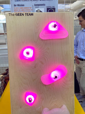
Our main focus in testing our project was making sure it is visible and lights up enough in dark areas. We tested out product at CU's climbing gym in the Rec Center. We asked our client to give feedback about different colors and brightness along with its impact in dark and light areas of the gym. This was important to us because if our product was not an effective solution, there would be changes that would need to be made. Our client found that the hand holds were easy to see in both environments, even when the hand hold was high above their head or far away. They commented that the hand holds were even bright enough to be useful for climbers with only light/shadow perception. A visually impaired climber’s climbing partner could adjust the brightness of the holds throughout the route in order to highlight the location of the appropriate hand holds to the visually impaired climber.

Handhold in Dim and Bright Areas
Future Iterations
Future plans with the product consist of completing a full 15 hold set. Our current set up only allows for 4 holds to be powered. We would need to adjust out power distribution box in order to supply enough power to light up 15 holds. We also hope to improve our wire system. One of the things we would change is the fact that you can see the wires coming out of the hold. We would want to hide those inside/behind the hold to reduce the risk of climbers stepping or slipping on the wires that insert into the bolt.
Lessons Learned
I learned so much from this project. It was an amazing feeling at the end of it to see what we were able to accomplish. We truly brought our initial idea to life. By being responsible for the code and communication aspects of our project, I gained a lot of experience in the area. I had never worked with any of the components we used in our project so I now know what microcontrollers are capable and how they can be applied to other projects in the future. I have already applied by knowledge of Neo Pixels to another project in a different class. Blynk is also a very powerful tool I hope to implement in the future because of its ability to control a system from a phone. It is a great way to incorporate an app into a project without creating an entire app on my own.

.jpg)